Oil Pump Jack
Made by Greg Dorosh
This 3D model was created in 3D studio max. It is a picture of a pump jack that is designed to pump oil out of the ground. These can be seen all over in Alberta prairie’s where there are pockets of oil under the ground.
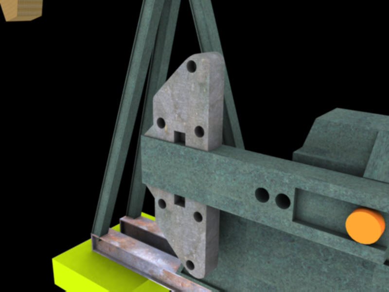
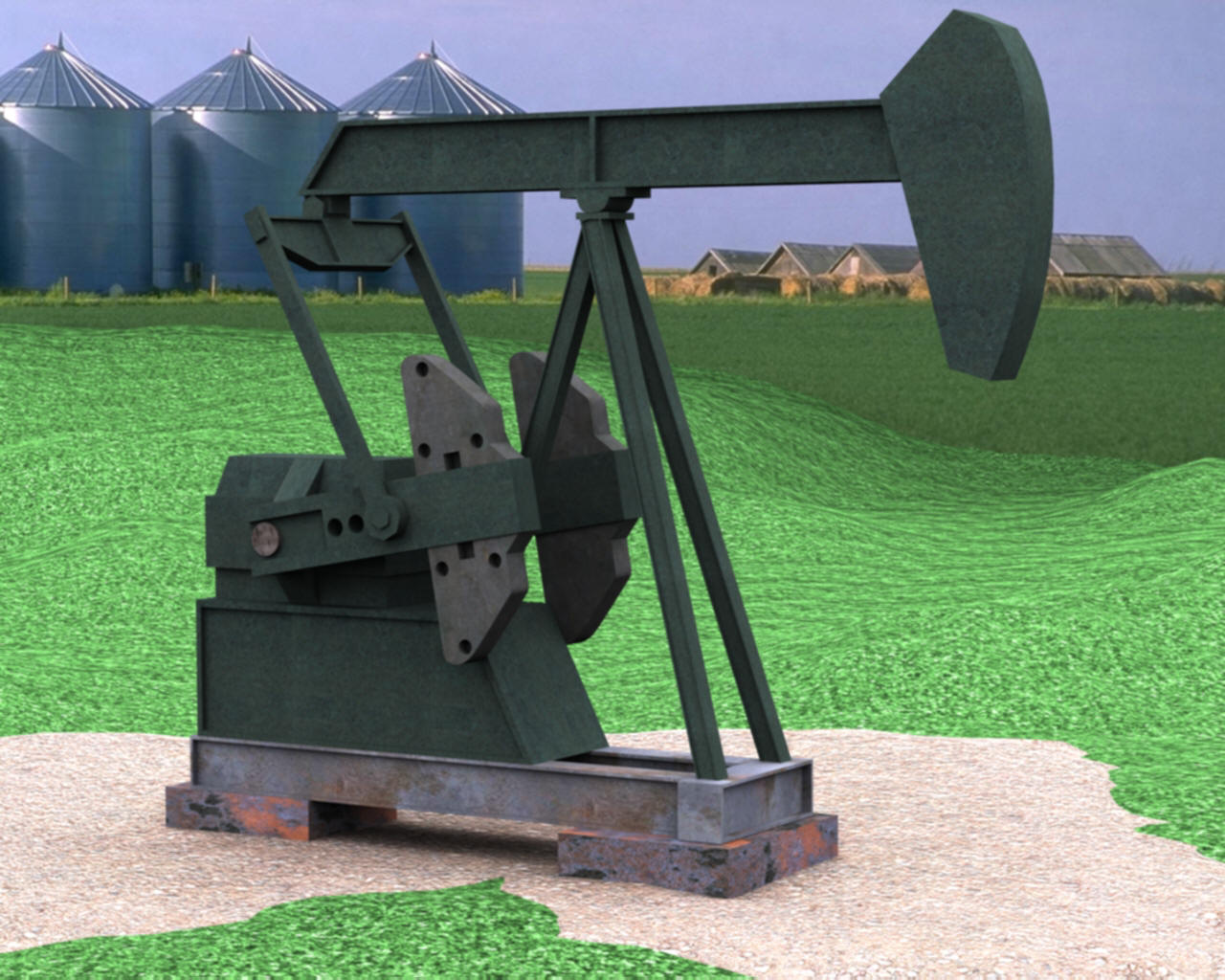
The first object that was created as part of the jack was the heavy weight on the front of it, which resembles a horse head. The front of it has a round shape; the best way to do this is to draw it. Since there was nothing that I was going to ‘cut’ out of this object, I used a common technique called lofting to create it. Lofting involves “expanding” a 2D spline (lines, rectangles, etc.) into a 3D one. If the object you want to represent in 3D has a fairly uniform shape (rectangles, triangles, cylinders…) lofting was a good way for me to use my drawing skills to ‘draw’ the side of the object, and allowing 3D Max to ‘extrude’ the 3rd dimension. Here is a screen shot looking at the 2D spline beside the 3D object.
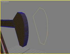
This technique was the basis for almost all of the ‘parts’ of my pump jack. To get the I-beam look in the tripod for example, I created a cube and sized it. Then I ‘drew’ a rectangle a bit smaller than the side of the cube, and lofted it into 3d. With this new loft, I placed it ‘inside’ the cube somewhat. Then I used a modifier called Boolean to subtract the newly created loft out of the original cube, leaving behind an indent.
The most difficult part of this project was getting used to the 3D studio environment. I had used it before, but there is always new ways of do things in 3D Studio. A lot of time was spent re-doing a technique to make whatever part you’re working on better. Once you’ve learned a new trick, you always get better with more practice. Another time consuming part of the project was getting the textures to look realistic. At first I didn’t understand how some of the UVW mapping tools worked to ‘paint’ a picture across different types of surfaces. But, with a bit of practice, I learned how to map the textures faster which allowed me to concentrate on different setting to add realism.
There were a few objects in this pump jack, like the tripod, and the bottom I-beams, which I was able to ‘clone’ and rotate to avoid repeating some time consuming steps (like making sure the I-beam looks symmetrical). For example, once I was satisfied with the textures and shape of one I-beam from the tripod, I just cloned it twice and rotated the new ones into place to make a tripod.
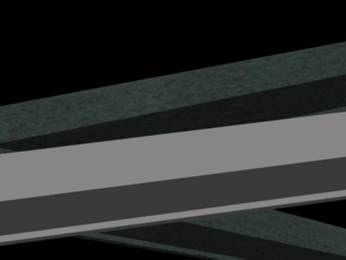
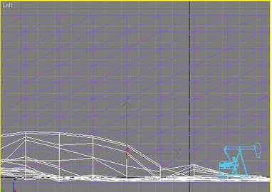
After being satisfied with all of the different parts to the pump jack, I had to place them in the right locations (by rotating, and moving along an XYZ co-ordinate system) and joint them together. This was done by either using Boolean (Union) to remove un-needed polygons that would be ‘inside’ other objects from placing objects together to give them shape, or using an ‘Attach’ function of Max to make the object one big pump jack. Now I was ready to put it into a simple scene. The scene was done by using 3 box objects, one for the background picture, one for the ground and another for the gravel around the pump. To make an un-even ground, applying a ‘displacement’ technique directly to the box object worked well. This technique involves using a grayscale image (darker places representing higher points of the ground, white meaning ground level) and mapping it on the box, then applying a ‘strength’ (in a negative direction because in 3D Max dark usually represents shadows, but painting higher ground in Photoshop is easier) to displace the box in some direction. Here is an example in wire frame:
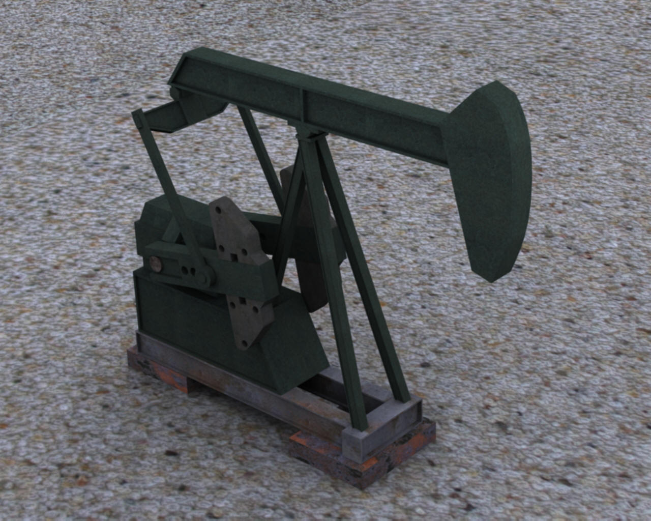
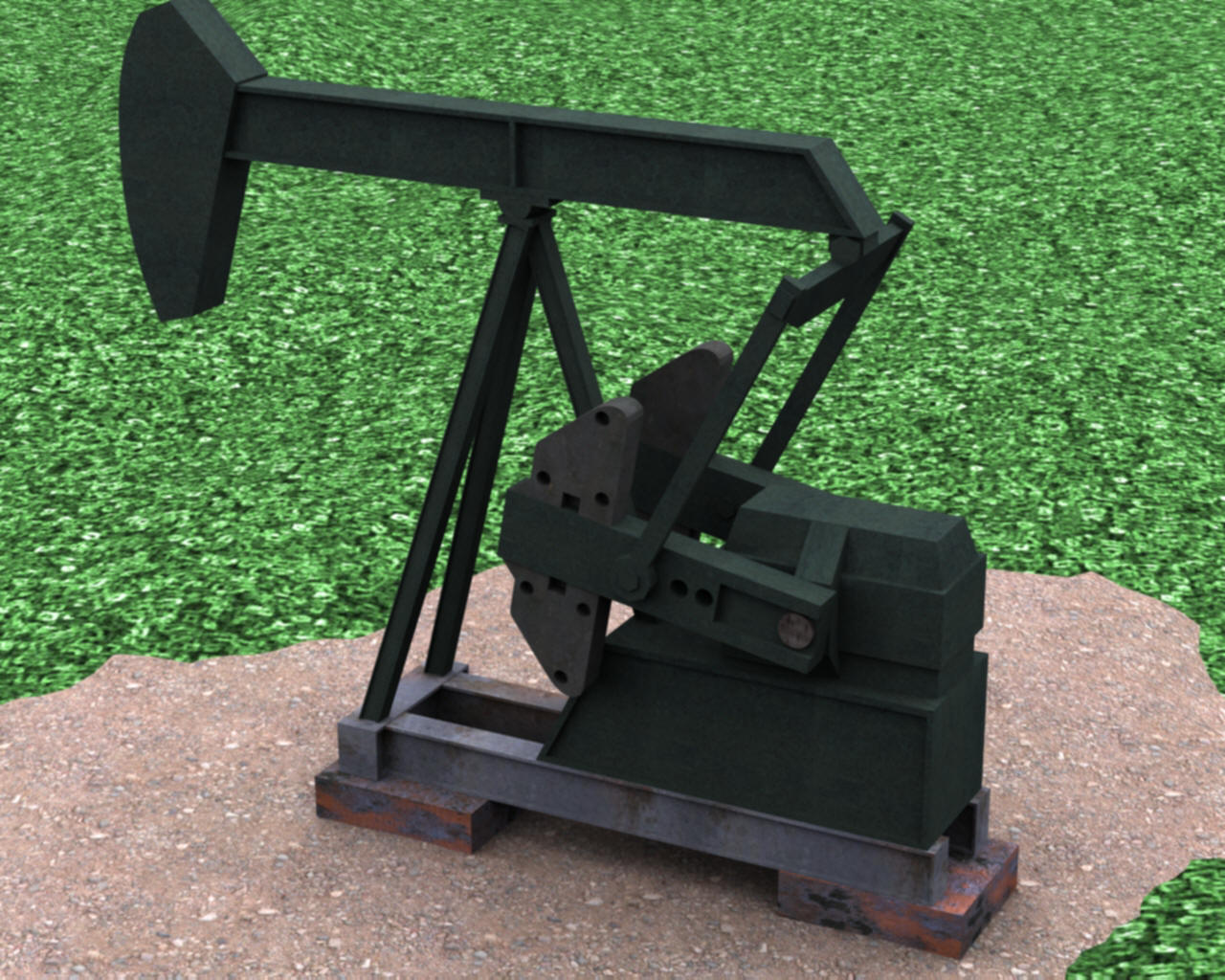
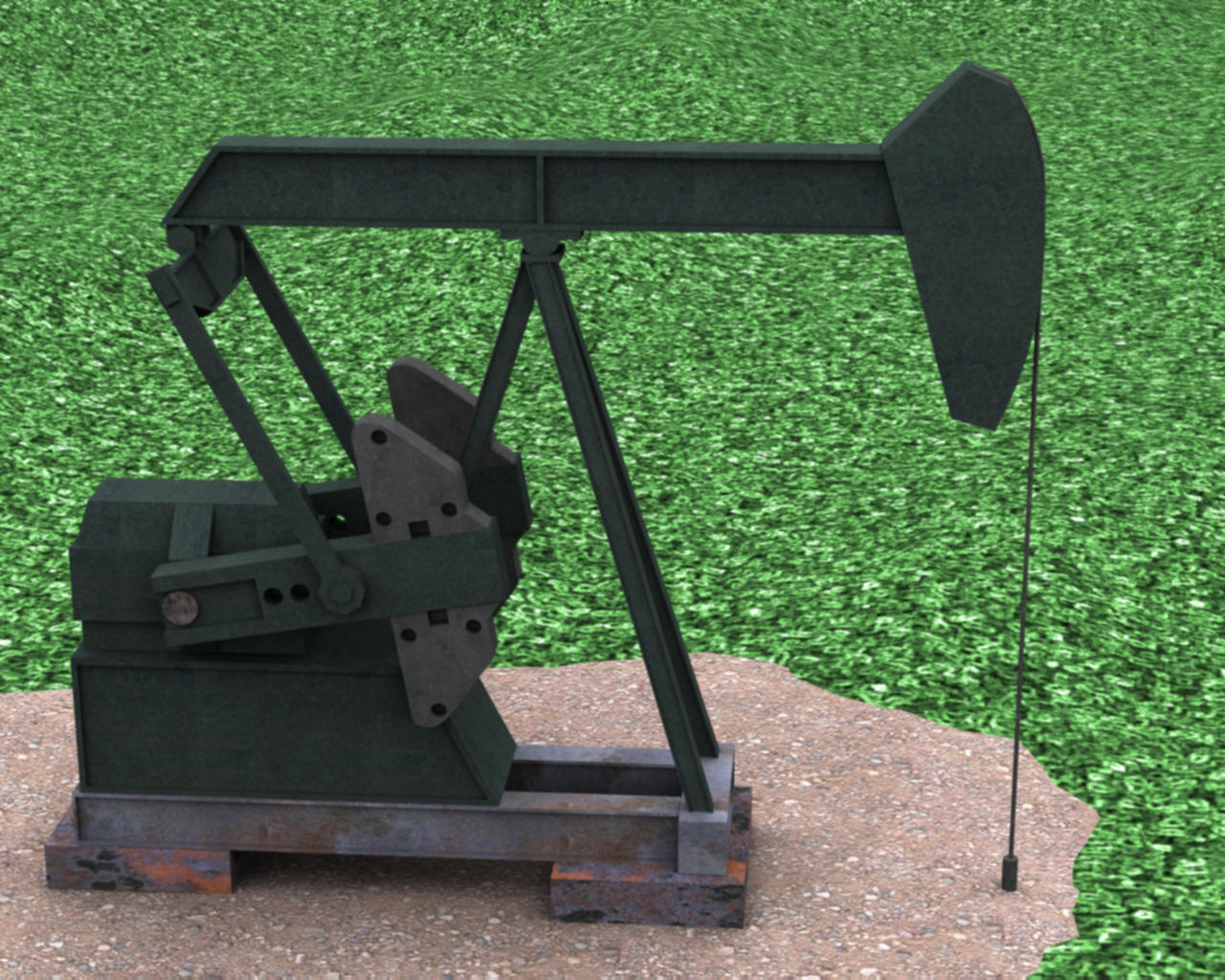
Here are a few pictures using different view angles and some light differences