Fabrication
Modelling

This was my first time doing any kind of 3D modelling, so the first thing I did was install Blender and do a few tutorials to familiarize myself with the interface a bit and to learn some basic modelling tricks. After I was moderately comfortable, I decided to dive right in and start modelling my sonic screwdriver. Despite having gone through the tutorials, I was (justifiably) intimidated by the beast of a program which lay before me. Was I about to dive into hell on Earth? As River Song would say, "Spoilers!"
When I first created my new project in Blender, all it offered me was this measly cube. I thought to myself, "Maybe it's bigger on the inside. Maybe I can use it to travel into the future to find out what sort of grade I would get on this project, and adjust my work ethic accordingly. I thought wrong. It was just a cube. Darn.

As any reasonable human would do, I promptly discarded the cube and began work with a simple cylinder. Now, you might be thinking, what could go wrong when using a simple cylinder? A few weeks ago, I may have agreed with you. Cylinders worked quite well as a base for much of my model, but once modified a bit, smoothing them can quickly turn into your worst nightmare. They react in all manner of undesireable ways which the novice modeller would not expect. Granted, a more seasoned Blender user would likely know all the ins and outs of creating good meshes, but that certainly was not inclusive of me. Despite having to redo many pieces of my objects, sometimes multiple times, I was able to learn a lot about the importance of good topology in 3D modelling. But I do digress, more on that later.

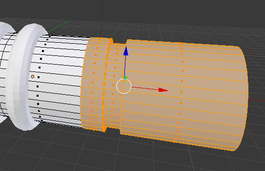
I needed to create a sort of "rolling" height change effect in part of the grippy bit of the screwdriver. In this image you can see I was experimenting with extruding and scaling to get this effect, but I was not too pleased with the results.


I found that wrapping toruses around my cylinder produced a much better effect. I was also able to cut one in half and extrude it to create the big, long section of the grippy bit. This gave a nice "rolling ramp-up" look to the transition.
The part to the right of the grippy bit (for simplicity's sake, I will reference things in a "business-end-on-the-left" coordinate system throughout my discussion) would need to have a different material when I got to that stage of things, but I didn't want to introduce extra complexity by making it a separate object. I learned that I could use a loop cut on the left hand side of this new section to create a separation, then simply select the relevant faces, and assign a secondary material to them (I will discuss materials in more detail later).


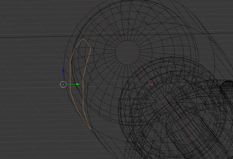
I got creative when making the tail piece and joined a modified cylinder (the body) to a modified sphere (the end cap). This turned out not to work so well when I smoothed it. I ended up with some strange dips and darkened faces. To be honest, I am not quite sure what was wrong with it. Also pictured are the claws on the left side of the tail piece. I made them quite detailed by subdividing a lot then deleting faces to sculpt them. Later when I tried to connect them inwards and smoothed them this turned into a nightmare. Again, keep in mind this is my first ever 3D project, and I simply did not have the experience to know how to do this properly.


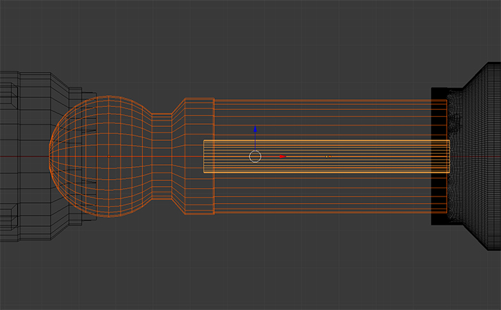
I ended up redoing the tail piece, instead making the entire thing out of a modified cylinder, which I extruded and scaled many times. I also redesigned the claws, simplifying them somewhat, but still had to be creative in my approach. Note the supporting edges near each edge. These are often critical in creating a good mesh, preventing the edges from being warped when smoothed and giving control over the sharpness. The pink edges which you see are creased edges, which is another method of getting a sharp edge when smoothing.

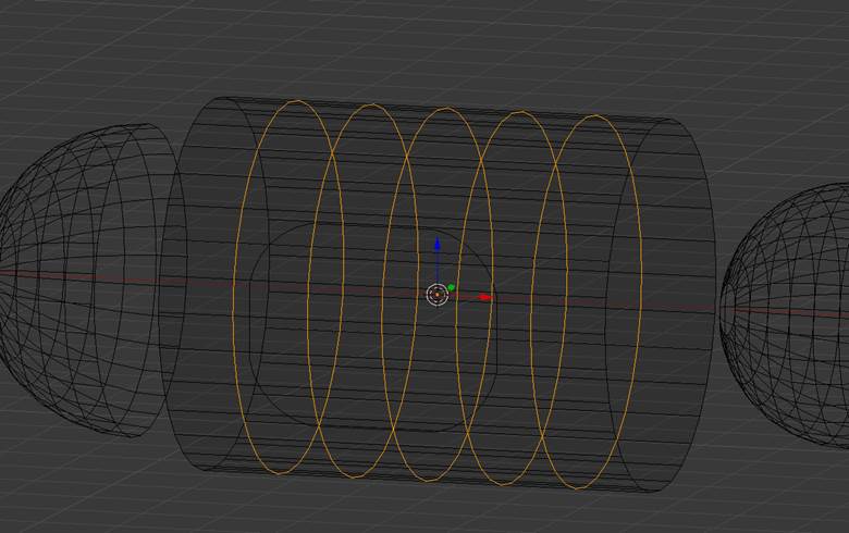
I was able to create the base shapes for the rest of the screwdriver out of cylinders and a sphere without too much trouble. But do not be fooled. Much of the struggle is still yet to come. I am leaving out my original (quite involved) attempt at the claws for the far left cylinder, since I ended up redoing that whole piece anyway.


As I said, I ended up redoing the entire far left cylinder piece, but it is worth showing how I originally did it, if only as a cautionary tale to those who dare to blend in future times. I originally punched holes through the cylinder using Boolean difference modifiers in combination with a couple of modified cylinders. This was a bad choice, but how was I to know? Nine times out of ten it is a bad choice to use Boolean modifiers. They may create a great looking result at first glance but they simply do not create good mesh topology, introducing nonsensical triangles and unnecesary faces. When it comes time to smooth, you will be sorry if you do not heed my warning.

For my second attempt at the far left metallic cylinder I started with a rounded rectangle (created from a modified circle) and a cylinder. I added loop cuts to the cylinder to create additional edges and vertices in and around the rounded rectangle. You will see why shortly.
Next I projected the rounded rectangle onto the cylinder using a shrinkwrap modifier to make it conform to the cylinder's curve and joined the two meshes.
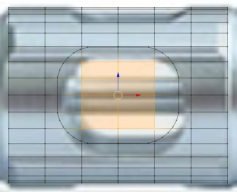
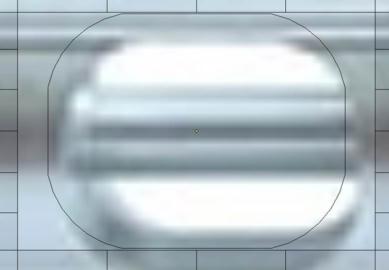
Remember those extra edges and vertices I created earlier? At this step I selected those which were inside of the rounded rectangle and deleted them, effectively leaving the rounded rectangle floating in a rectangular hole. The image you see in the background was a reference image I used as I worked. It is listed in my citations.
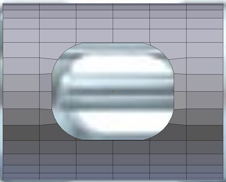
I then stiched the edges together by selecting them and adding faces. Instead of repeating this whole process for the back of the cylinder, I simply deleted the back half and used a mirror modifier to make a reversed copy of the front half.
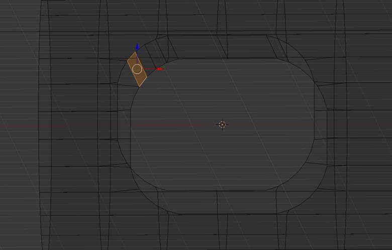
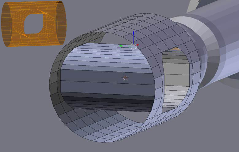
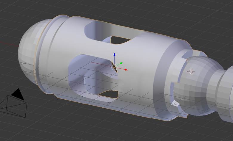
The inner cylinder was created by joining the corresponding edges of the two rounded rectangles with faces. Notice how clean the mesh topology looks? No extra faces. No weird triangles. But I was not done yet! I still needed to punch a verticle hole through the mesh.
The process was similar for cutting the verticle hole, except I now had to punch a hole through the inner cylinder as well. To save time again, I deleted the bottom half and used a mirror modifier when I was finished. Then I simply matched up the edges and added faces between them to connect everything (not pictured).
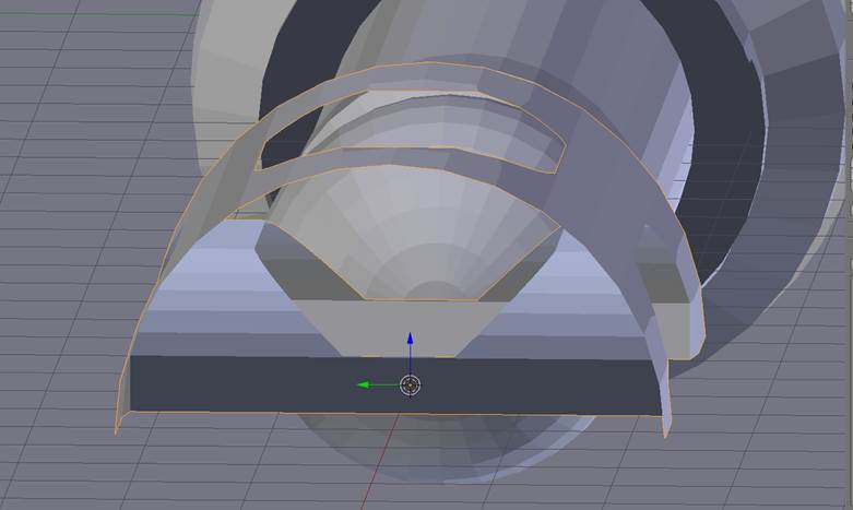
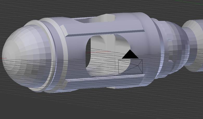
I extruded and scaled several times to create the rest of the shape you see here. Smoothing and subdivision surface is turned on in this picture to give you an idea of how well it works with this new mesh. It is also worth noting that you usually need either supporting loop cuts near edges or an edge split modifier when using a subdivision surface modifier for smoothing on a cylinder. The results are a bit surprising to a novice modeller such as myself if you do not use one of these two methods.
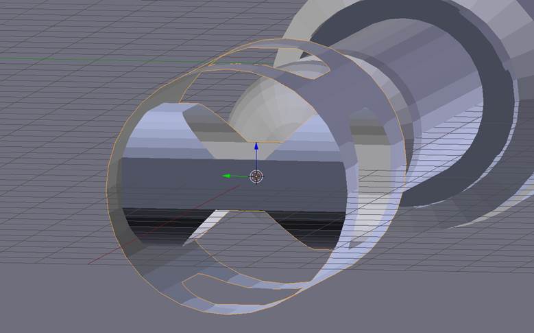
Here you can see the claws and ridges have been added. It was a fight to get them looking like this as every time I would go to smooth, faces suddenly had holes in them. I solved this by using the subdivide tool strategically on many individual faces. It was tedious to say the least.
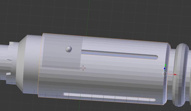
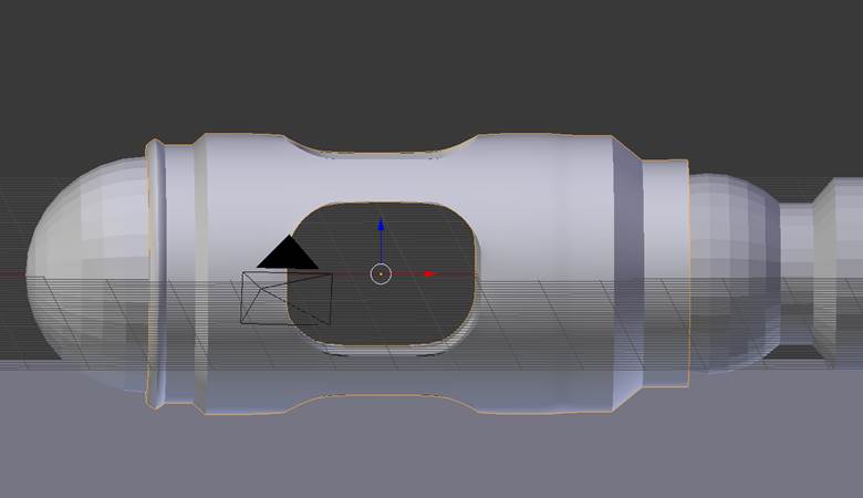
The slits in the grippy bit were created in a similar fashion to how the interior cylinders were created in my previous discussion, only without connecting faces. The button pad(seen resting on top of the grippy bit) was created by making a copy of the grippy bit, scaling it larger, deleting the sections which were not needed, and adding a solidify modifier to give it thickness. By using a copy of the grippy bit as the base, I was able to ensure that the button pad conformed to its shape. The glass button on top was created by modifying a sphere. There is also a cylinder inside of the grippy bit, which acts as the blue interior of the screwdriver. The claws you see to the left in this picture were adapted from a copy of the claws from the far left metallic piece.

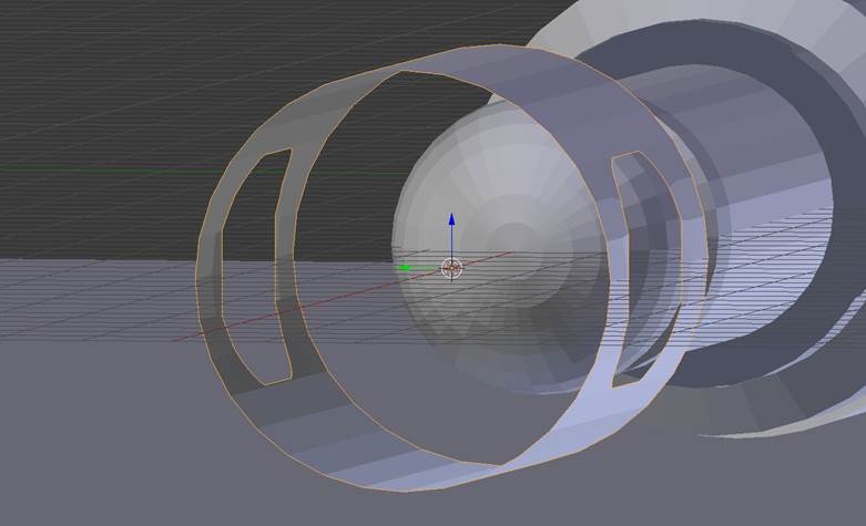
The blue light is comprised of three components: the outer shell, the inner sphere, and a point light. The outer shell was created by modifying a sphere. I started by discarding the rear half and a little bit of the front, then I extruded and scaled on both sides to create an interesting design. I also applied a solidify modifier to it to give it some thickness. The inner sphere acts like the light (maybe an LED) which you would see shining through the shell and the point light was there to give the light a bit of bloom and make it look more realistic. I hid the near half of the outer shell in the picture above to make it easier to see the inner components.
There are three pieces of the screwdriver which I have not discussed directly up until now: the metallic sphere, located next to the claws of the far left metallic piece, the glass tube, and tube inside the glass. I cut off part of the right-hand side of the sphere and extruded the edges to create a cylinder leading into it. There is nothing worth noting for the glass tube and its inner tube -- they are both simple cylinders, scaled as necessary.
Materials
While experimenting with materials and reseraching online about them, I found that it is a very deep subject. Many people go to painstaking lengths to reproduce realistic materials down to the smallest detail, like how much light is refracted vs reflected. A lot of this can be achieved with the node editor, though it is quite difficult to get the hang of. With some materials, such as silver metallic material which I used for a few parts of the screwdriver, were beautifully simple. I created it using a glossy white material in combination with HDRi lighting (see below).
The blue light's outer shell was created using a combination of Glass BSDF (set to light blue colour) and Transparent BSDF (set to dark blue colour) shaders, with the glass being used for light rays and the transparent being used for shadow rays. There is a small sphere inside set as a white emission source material, acting as an LED light source, with a point light just in front of it to create a bloom effect.
The blue inner cylinder inside the grippy bit and the yellow cylinder inside the glass tube were both Diffuse BSDF materials, set to the appropriate colours. The glass tube was a simple Glass BSDF material set to white.
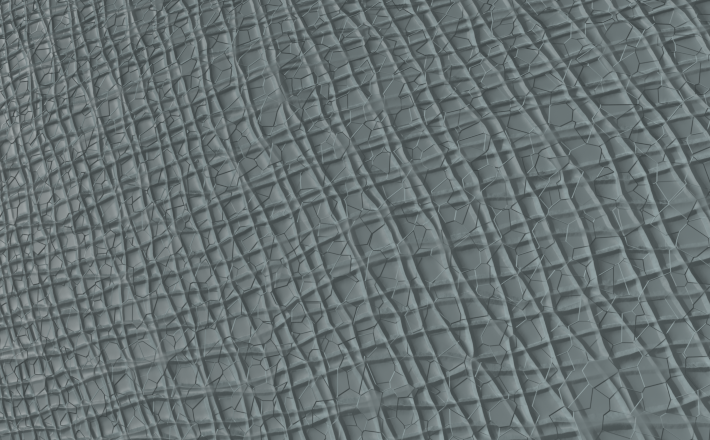
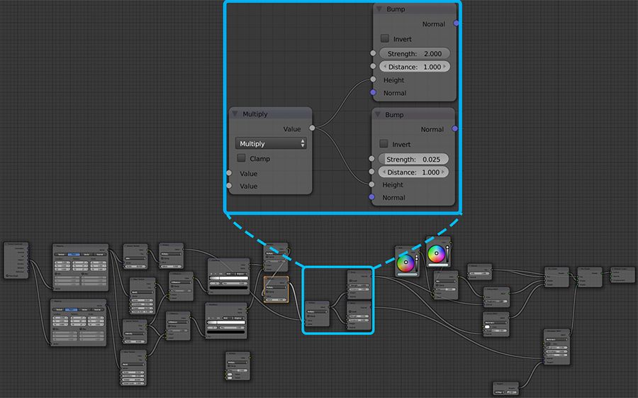
I was able to reference a book on Blender materials (see citations) as a starting point for some of the other materials. One particularly complicated material which I used has the look of cracked leather. I based it off of a leather material in the book, which was quite smooth to start off with. That material in itself was quite complex, and was comprised of many, many nodes. After some experimentation, I eventually discovered that I could create a rough, cracked look by adjusting the nodes shown in the loupe in the diagram above. The multiply node on the left was originally set to add. I set it to multiply to intensify (polynomialy) the height values of the bump nodes. I also modified the strengths of the bump nodes, increasing the gap between the two values. If I am being honest, a lot if this was trial and error. This stuff is complicated.
The material for the black tailpiece was created using a rubber material tutorial from the above mentioned book and simply changing the colour to black.
Lighting
I did some research before I started working on lighting my scene, since I wanted to really bring out the materials I had chosen. Lighting a scene in a way that makes the materials look realistic while still producing a dynamic image that really pops is definitely an art. It turns out that you can actually use high dynamic range (HDR) images to light a scene in Blender. I knew about high dynamic range (HDR) images from my experience with photography. Basically these are images which are created by combining multiple exposures of the same scene in order to get as much detail from the shadows, to the midtones, to the highlights as possible. It was, however, news to me that they were used in 3D modelling. After doing some more research, I found an image to use as a light source and set it up in Blender. It looked great! The only problem was that this introduced some noise when using a low number of samples, and also took considerably longer to render in general. It took some experimentation to figure out the "sweet spot". I was able to render a 1920x1080 image at 100 samples in around 6 hours. Yes, this was still a bit extreme, but I was at least able to render an image overnight. You might be thinking, "That's crazy! He has like 5 rendered images! That must have taken forever!" Well, you would be right, except for the fact that I spent even more time rendering since I threw some away.