| |
 |
| |
| |
| |
| |
| |
| |
| |
| |
| |
The 5 bend variant is similar to the 6 bend staircase model. It relies on pedestals, pillars and lanes, and also adds the notion of a climb which extends above the vertex. A series of planes under the layout is also introduced. Routings are always done from a lower vertex V to a higher vertex W (just as in the 6 bend variant).

|

|
|
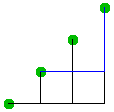
6 bend model side view. The vertices form a staircase and all routing is
done below the staircase formed by the vertices.
Routings to the top port of W do go above the vertex but are limited to the region immediately surrounding the vertex. The region above the bounding boxes around the vertices is unused. |
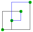
5 bend model side view. The vertices form a staircase as in the 6 bend model. However routing is now done both above and below the staircase formed by the vertices. |
As in the 6 bend variant the 5 bend model has a fixed number of planes (layers) associated with each vertex. These planes are used to separate the lanes from each vertex to ensure that no crossings can occur. The 5 bend model has 6 planes associated with each vertex: 4 in the vertex's neighbourhood, and 2 planes that are underplanes and are at a distance below the vertex that depends on the number of vertices in the graph. It is these underplanes that lead to the O(n) running times of insertions/deletions of vertices.
In the 5 bend model routing may occur in four regions: In the space immediately surrounding the vertex, in the space above the vertex V but at the plane level of W, in the space below W but at the plane level of V, and finally on the underplanes of any vertex V. These are detailed in the 5 bend layout page.
Lanes below the staircase route from one port to multiple ports. Lanes above the staircase route to one port from multiple ports.

|
Self loops are not generally possible in the 5 bend variant of the staircase. This is due to ports on the opposite side of the vertex (North to South, West to East, Top to Bottom). It takes at least 4 bends for an edge to reach the opposite sides port. An inspection of possible routings shows that any 4 bend routing of this nature will possibly intersect internal routings, or pillars, lanes, and climbs. This leaves the possibility of a 5 bend routing but a 5 bend routing is impossible in this case. The argument is as follows: the ports on the opposite side of the vertex lie on the same plane (2 of them actually), and any 4 bend routing (which is the minimal routing to these opposite side ports) lies along one of these 2 possible planes. A fifth bend at any point will take us off this plane. If we use a bend to return to the plane we are one bend short of being able to reach the port. If we don't use a bend to return to the plane then we cannot enter the port on that plane. |